TBM Wheel Speed Sensor 87-93 Fox Body Ford Mustang Spindle
$289.00 – $298.00
$274.55 – $283.10 Each - Free Shipping
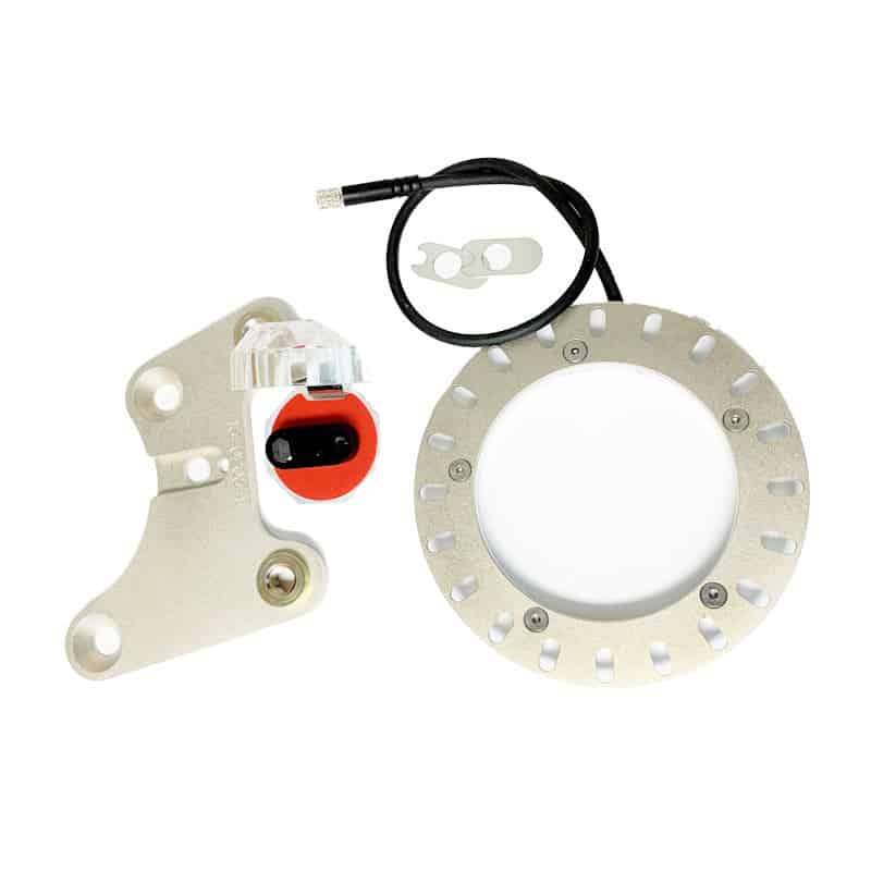
TBM Brake Wheel Speed Sensor Kit for 87-93 Ford Mustang Fox Body. This is a direct kit for TBM 87-93 Mustang Brake Hubs.
- 20 Tooth Tone Ring for high accuracy even at low speeds
- Caliper Bracket with sensor mount
- Bolt in installation
- Rife Sensors Hall Effect Sensor with shims
- Optional Cable Lengths
Sensor Wiring
Rife Sensors Hall Effect Speed Sensor is a true Zero-Speed, Low-Jitter, High-Accuracy sensor used for sensing ferrous targets, tone rings or gear teeth. Typical applications are wheel speed, driveshaft speed and position sensing. At the moment, we are not recommending it for crankshaft or camshaft signaling although those applications may be developed in the future. The Rife Sensors Hall Effect speed sensor is based on the Allegro Microsystems ATS627LSG position sensor IC. The IC is packaged, along with the necessary electronics, in a billet aluminum housing and sealed with epoxy. All of the signal conditioning is done within the Sensor Body itself and requires no external configuration. The connector is a sealed
M5 3-pin connector, cables are available through RIFE Sensors in a variety of configurations and lengths.
Pinout: Pin 1 Signal out – Brown Wire*
Pin 2 Power (Vcc) – Black Wire*
Pin 3 Sensor Ground – Blue Wire*
*Wire colors when using RIFE Sensors supplied cables
Mounting: 8-32 UNF female thread
RIFE Hall Effect Speed Sensor Specifications
| Min. | Typ. | Max. | |
|---|---|---|---|
| Input Voltage (Vcc) | 3.3V | 24V | |
| Supply Current | 7 mA | 12 mA | |
| Rise Time | 10uS | 20 uS | |
| Air Gap | 0.030″ | 0.060″ | 0.100″ |
| Max. Speed | 0 Hz | 12,000 Hz | |
| Weight | 6.5 g | ||
| Length | 1.125 in. | ||
| Width | 0.500 in. | ||
| Height | 0.600 in. |
Sensor Installation
The target wheel must sweep across the sensor face perpendicular to the long axis, it may work in the parallel axis, but accuracy will suffer. The Hall Effect elements (there are 2) within the exposed IC are aligned with the “dimples” on the edges, special care should be taken to align these dimples with the teeth of the target. The mounting bracket must have enough rigidity to hold the sensor stable, excessive vibration could show up as noise in the output signal. Runout: the sensor has been designed to accommodate the typical runout seen in racecar applications, however, care should be taken to keep it to a minimum. Any runout greater than .020” should be addressed. Additionally, any runout must not cause the air gap to exceed the maximums and minimums listed in the table above. The output voltage of the square wave signal will equal the input voltage, please make sure that your ECU is compliant with this voltage level. Best practice is to use the voltage level supplied on your ECU’s sensor bus. Typically, this is 5V.
Sensor Ring Installation
Hub Mount
Fits TBM hubs only
TBM wheel speed sensor kit mounts to TBM manufactured hubs and will provide accurate wheel speed
calculation when paired with an appropriate hall effect sensor.
Kit includes:
20 “tooth” wheel speed ring
Hub adapter
6-32 flat head mounting hardware
Loctite 680 mounting adhesive.
Installation
TBM Wheel speed ring kit should only be installed by qualified personnel
Installing the hub adapter:
- Inspect the hub adapter ring, you will note that one side has a rounded chamfer on the ID, this
side goes against the hub. - Clean both the hub and the hub adapter ring removing all grease, oil, and dirt. Use a nonresidue cleaner such as brake cleaner or alcohol, let dry.
- Test fit the hub adapter ring on the hub making sure it seats completely against the hub face.
- Using the LOCTITE 680 provided, completely coat the seal boss on the hub and interior mating
surface of the hub adapter ring. - Install the hub adapter ring to the hub using a twisting motion, make sure the hub adapter ring
is completely seated against the hub face. - Let cure 2 hours before proceeding, adhesive will fully cure in 24 hours.
Installing Wheel Speed Ring
- Inspect hub/hub adapter ring assembly to make sure hub adapter ring is completely seated against hub face, if it is not, please call TBM for instructions on removal/replacement.
- Utilizing the included hardware, install the wheel speed ring on the hub adapter using an appropriate thread locking compound (Loctite 242 “blue” or similar), do not over-tighten screws.
| Cable Length | 1 Foot, 3 Foot, 6 Foot, 9 Foot |
|---|
Be the first to review “TBM Wheel Speed Sensor 87-93 Fox Body Ford Mustang Spindle” Cancel reply
You must be logged in to post a review.


Reviews
There are no reviews yet.