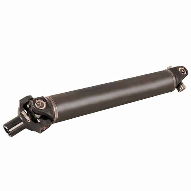
Strange 3 1/2″ Chrome Moly Driveshaft w/Forged 1480 Ends, Solid U-Joints U1706
$709.00 Each - Free Shipping
Strange Engineering’s Seamless Chrome Moly Driveshafts are constructed from .083″ wall 4130 seamless chrome moly tubing for exceptional strength. 1480 Solid U-joints are included and installed in the 4130 chrome moly forged ends with additional material in critical areas.
- 3 1/2″ O.D.
- 4130 .083″ Chrome Moly Seamless Tubing
- 4130 Chrome Moly Forged Ends
- Includes 1480 Solid U-Joints
- Also available with 1480 Transmission Yoke
Measurements
Should be taken on level ground, full weight on all four tires, vehicle at ride height, and pinion angle set. If the rear yoke is smaller than a 1350 series, it may be the time to replace it before proceeding. The driveline is only as strong as the weakest link and a new yoke will change your measurement.
DRIVESHAFT ONLY – NO TRANSMISSION YOKE: Push the transmission yoke all the way in until it bottoms, pull it out 7/8” and measure center to center. This is the ”C” dimension. If you are not using all 1350 series yokes, supply the “D” and “E” from any that are not and note which end they belong.* Your transmission yoke will need to be sent-in to properly balance the driveshaft.
Critical Driveshaft Speed
Driveshaft Critical Speed – Defined as the lowest rotating speed at which the natural frequency of the driveshaft is reached. Centrifugal force excites the driveshaft causing extreme vibration which can lead to catastrophic failure.
1/2 Driveshaft Critical Speed – Vibration of a driveshaft can occur at rotation speeds centered around 1/2 of of the critical speed. This occurs because the standard U-Joint cycles or rotates twice for every one revolution of the driveshaft. This applies more to street cars with longer driveshafts that will see cruising or highway driveshaft speeds at or near the 1/2 critical speed. If this is a problem several steps can be taken to combat this vibration.
-
- Verify that the balance and the runout of the driveshaft are within spec.
- Reduce the u-joint angles keeping them both equal or the pinion 2 deg. lower.
- Disconnect the driveshaft from the pinon yoke, rotate 180 degrees and reinstall.
- Slide the driveshaft out of the transmission, rotate the slip yoke 90 degrees and reinstall.
- Change the length of the driveshaft.
The Table below gives the driveshaft length verses 1/2 critical speed and 80% of critical speed for 3″ O.D. and 3 1/2″ O.D. driveshafts. The 80% of critical speed rating provides for a 20% factor of safety. Figuring your application at or below the 80% of critical speed will be safely out of the realm of potential catastrophic failure.
The table is based on the following information:
- Tubular driveshaft with .083″ wall thickness.
- 1350 series u-joints.
- 4130 seamless tubing.
- Driveshaft length shown as “C” dimension.
- Driveshaft style shown as below.

| Driveshaft Length (in) | 1/2 Critical Speed (RPM) for 3″ O.D. | 80% Critical Speed (RPM) for 3″ O.D. | 1/2 Critical Speed (RPM for 3 1/2″ O.D. | 80% Critical Speed (RPM for 3 1/2″ O.D. |
|---|---|---|---|---|
| 35 | 7900 | 12640 | 9250 | 14800 |
| 37 | 7100 | 11360 | 8300 | 13280 |
| 39 | 6400 | 10240 | 7500 | 12000 |
| 41 | 5750 | 9200 | 6750 | 10800 |
| 43 | 5250 | 8400 | 6150 | 9840 |
| 45 | 4800 | 7680 | 5600 | 8960 |
| 47 | 4400 | 7040 | 5150 | 8240 |
| 49 | 4050 | 6480 | 4750 | 7600 |
| 51 | 3750 | 6000 | 4350 | 6960 |
| 53 | 3450 | 5520 | 4050 | 6480 |
| 55 | 3200 | 5120 | 3750 | 6000 |
| 57 | 3000 | 4800 | 3500 | 5600 |
| 59 | 2800 | 4480 | 3250 | 5200 |
| Weight | 23.95 lbs |
|---|
Be the first to review “Strange 3 1/2″ Chrome Moly Driveshaft w/Forged 1480 Ends, Solid U-Joints U1706” Cancel reply
You must be logged in to post a review.


Reviews
There are no reviews yet.